
FlexiForce Integration - Phase 2 - Proof of Concept
6 Phases of Sensor Integration Blog Series
In post 1 of our 6 Phases of Sensor Integration, we acknowledged that when embedding components like sensors, each application has unique nuances and there is no “one size fits all” approach. However, following an established framework and leveraging certain tools can help structure the process and reduce the risk of costly, time-consuming mistakes. Last week, we addressed Phase 1 – sensor characterization. In that post, we shared one design team’s approach to collect data on how the FlexiForce sensor would perform with the circuits and material interfaces they were considering for their design - a portable, wearable device medical device. The data they gathered in that phase helped them feel confident in their circuit selection.
This week, we follow the team as they progress to Phase 2: Proof of Concept. At this phase, the design team must verify whether they can successfully capture their intended measurement with the FlexiForce sensor and their selected electrical/mechanical configuration in a one-off representative mock-up of their application.
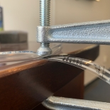 A plastic tube was placed between a sensor and a loading fixture
The intended use of the sensor in this application is to detect occlusion in an insulin pump. The team devised a concept with the FlexiForce sensor placed below a plastic tube comprised of material similar to that which would be used in the final design.
Using a FlexiForce Prototyping Kit, the engineers were able to effectively test the sensor in their concept using:
- A voltage divider analog circuit module that they selected during the characterization phase
- A polycarbonate load concentrator
- Open-source software, which allowed the team to monitor live force feedback
With this tool, the design team discovered that the current reference voltage of the circuit was not providing enough sensitivity to capture a robust measurement of the occlusion event. They were easily able to increase the reference voltage from 0.5V to 1.0V using the jumper on the board of the FlexiForce Prototyping Kit. This increase in reference voltage provided the increased sensitivity and resolution required to reliably capture occlusion in the tube.
After more testing, the team also determined that the polycarbonate concentrator was not providing the desired output, and opted to go with a stainless steel substrate for their concentrator.
Now that they have proven the concept, the team is ready to move on to the next design phase.
Ready to learn more? Download the 6 Phases of Sensor Integration to follow the team through each subsequent phase.
Are you Working on a Your Next FlexiForce Sensor Integration Project?Register from the form below to access the FlexiForce Integration Knowledge Base, an entire library of useful FlexiForce sensor integration documents, articles, videos, and other critical content. |
 |