
FlexiForce Integration - Phase 1 - How will FlexiForce Sensors Perform in My Application?
Secrets to a Successful Sensor Integration
As the drivers of innovation, engineers rely on their education, experience, and instincts to make important choices on their design journey. Every embedded technology has unique inherent properties and nuances, and decisions made early in the process can have a major impact later. Having an established framework can help structure the process and reduce the risk of costly, time-consuming mistakes.
Take thin, flexible force sensors for example. As consumers demand devices that are smaller and sleeker, more design engineers are turning to FlexiForce™ sensors because of their lightweight, conformable profile and low-power demands. While every journey a device takes from concept to completion follows a unique path, we have identified six core phases, or checkpoints, engineers encounter:
- Sensor Characterization
- Proof of Concept
- Prototyping
- Field Testing
- Final Embedded Device
- Transfer to Production
One design team was developing a next-generation, automated, wearable drug-delivery pump. They needed a sensor that could not only sense any relative expansions within the device, but it also needed to fit within a very tight space. We followed the team as they navigated their way through these six phases of design and compiled their learning covering the challenges they faced and what they learned throughout their process.
In Phase 1, the Sensor Characterization phase, engineers designing with FlexiForce sensors are looking to address the following questions:
- What is the fundamental performance of a FlexiForce sensor?
- How does a FlexiForce sensor perform with the circuits and material interfaces we are considering for this application?
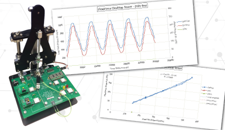 This particular design team needed a sensor characterization schematic. Instead of building a loading fixture and creating circuits from scratch, they used a FlexiForce Sensor Characterization Kit to streamline this process. The Kit includes a calibrated load cell in the loading fixture, providing an experimental control to compare against FlexiForce sensor output. This is an important element to characterization, as it provides users with an understanding of sensor capability and performance under known loads. This data will prove valuable in later design phases, as it provides a known baseline for performance that can be referenced when troubleshooting or debugging.
The engineers began by loading the FlexiForce sensor to the circuit, and applying the expected force and frequency to the sensor. They monitored raw sensor output from the Microview interface. To their surprise, the team found that the sensor output varied across the different circuit types, and when loading with different interfacing materials. After a few rounds of testing, they decided on a voltage divider.
With the Sensor Characterization phase successfully completed, the team was ready to move on to stage 2, Proof of Concept.
Ready to learn more? Download the 6 Phases of Sensor Integration to follow the team through each subsequent phase.
Are you Working on a Your Next FlexiForce Sensor Integration Project?Register from the form below to access the FlexiForce Integration Knowledge Base, an entire library of useful FlexiForce sensor integration documents, articles, videos, and other critical content. |
 |