FlexiForce A201 Sensor
$155.08


A201 sensors are trimmable and have a 3-pin male connector. The sensors are available in three force ranges: Low 4.4 N (0 - 1 lb), Medium 111 N (0 - 25 lb) and High 445 N (0 - 100 lb)*. The force ranges stated are approximations. The dynamic range of this small, versatile force sensor can be modified by changing the drive voltage and adjusting the resistance of the feedback resistor (see "How to Adjust the Force Range" within the Electronics tab on the left).

| Sensor Thickness: 0.203 mm (0.008 in.) |
|
Force Sensor Length 7.50 in
6.00 in
4.00 in
2.00 in
Sensing Size (Diameter/Width) 0.375 in
Standard Force 1 lbs
25 lbs
100 lbs
Temperature Range (Low) -40 F
Temperature Range (High) 140 F
Notes Most popular standard sensor, can be trimmed |
| Linearity (Error): | < ±3% of Full Scale (Line drawn from 0 to 50% load) |
| Repeatability: | < ±2.5% (Conditioned Sensor, 80% of Full Force Applied) |
| Hysteresis: | < 4.5 % of Full Scale (Conditioned Sensor, 80% of Full Force Applied) |
| Drift: | <5% / logarithmic time (Constant Load of 111 N (25 lb)) |
| Response Time: | < 5 µsec (Time required for the sensor to respond to an input force; Impact load - recorded on Oscilloscope) |
| Operating Temperature: | -40°C - 60°C (-40°F - 140°F) |
| Durability: | ≥ 3 million actuations (Perpendicular load, room temperature, 22 N (5 lb)) |
| Temperature Sensitivity: | 0.36%/°C (± 0.2%/°F) (Conductive heating) |
†All data above was collected utilizing an Op Amp Circuit. If your application cannot allow an Op Amp Circuit, consult the FlexiForce Integration Guide, or contact a FlexiForce Applications Engineer.
If your application cannot allow an Op Amp Circuit, consult the FlexiForce Integration Guide, or contact a FlexiForce Applications Engineer. If you prefer to build your own electronics, we recommend using a circuit similar to the diagram below. This will provide linear data, making it easier to calibrate the sensor.
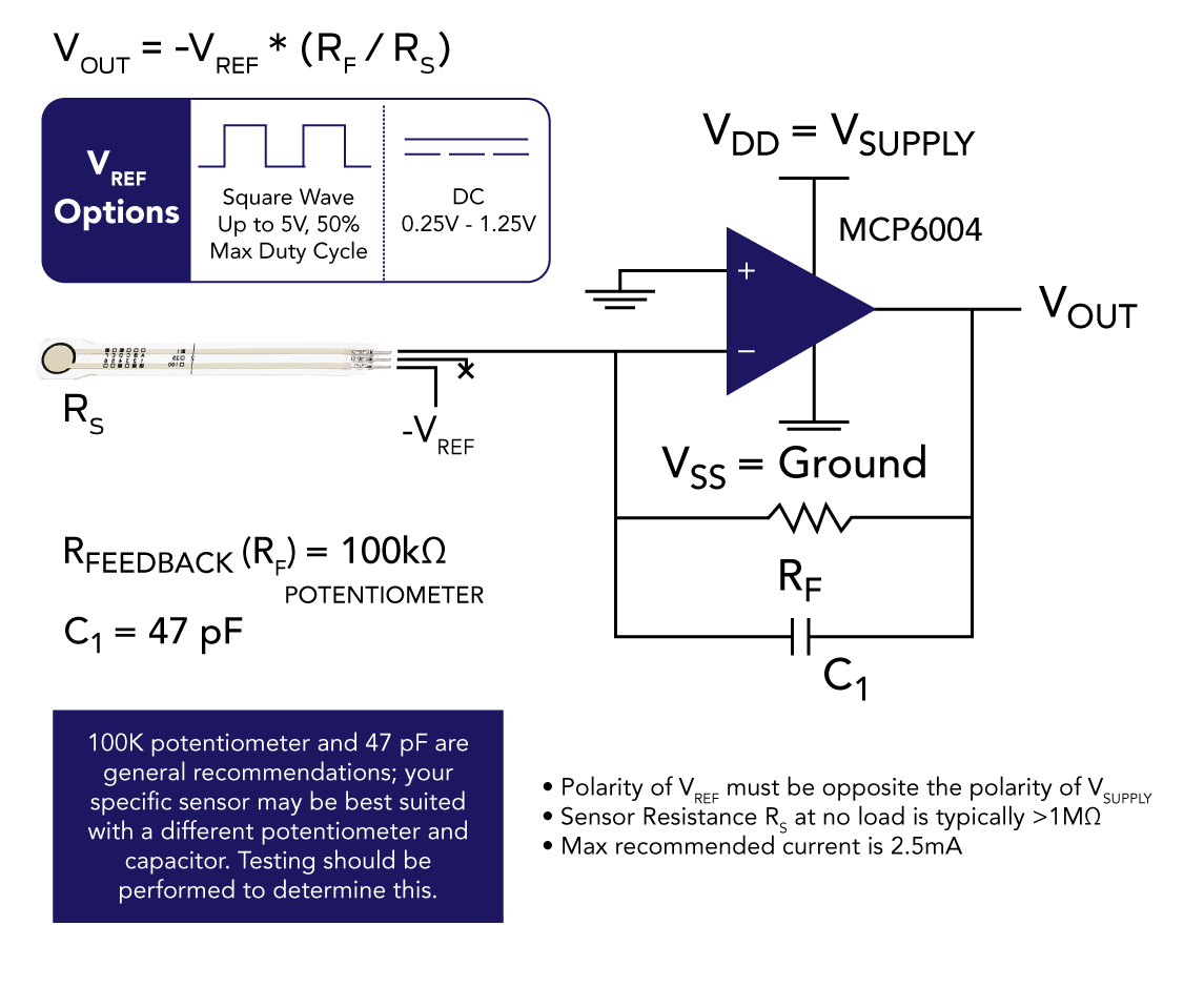
*In order to measure higher forces, apply a lower drive voltage (-0.5 V, -0.25 V, etc.) and reduce the resistance of the feedback resistor (1kΩ min.) To measure lower forces, apply a higher drive voltage and increase the resistance of the feedback resistor.
If you need help selecting the best measurement tool for your application, take a look at our comparison chart or contact us.
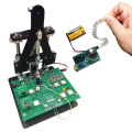
For: Design, OEM, and Product EngineersTekscan offers two products created to help design engineers proceed through all phases of the FlexiForce sensor-integration process. The FlexiForce Prototyping Kit allows you to efficiently progress your FlexiForce-embedded design through advanced integration phases. |
 |
| These peel-and-stick delrin FlexiForce Load Concentrators (otherwise known as "Pucks") are used to evenly distribute force across a FlexiForce sensor's sensing region, helping you optimize sensor linearity and repeatability. | 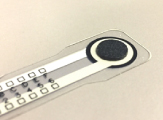 |
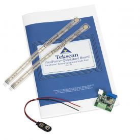
For: Design, Lab, OEM, and Product EngineersThe FlexiForce Quickstart Board is a single source circuit that provides signal conditioning to the sensor and a linear voltage output with an applied load. It can be quickly dropped into a prototype or easily designed into a finished product. |
 |
| While standard multimeters can be used, most do not provide a constant voltage supply (which is recommended for FlexiForce sensors) and they are more difficult to calibrate compared to the tools above. | 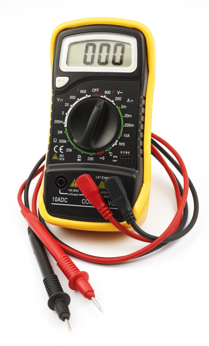 |
|
The FlexiForce Integration Knowledge Base is a comprehensive library of useful FlexiForce sensor integration documents, articles, videos, and other useful content. Follow the button below to gain access to critical resources for each important phase of the sensor integration process. |
 |
|
Additional Resources | ||
|
The FlexiForce Sensors User Manual |
4 Ways to Use FlexiForce Sensors in an Embedded Application |
|
| Click to Access | Get the eBook | Watch the Video |

The FlexiForce™ Sensor Characterization Kit is a time-saving, affordable tool enabling engineers and designers to understand how FlexiForce sensors perform in a controlled loading environment.

The FlexiForce™ Prototyping Kit allows you to efficiently progress your FlexiForce-embedded design through advanced integration phases.
Note: The FlexiForce Prototyping Kit includes an open-source software program designed specifically to help with the sensor integration process. Some code programming experience is necessary.
New and improved replacement for the OEM Development Kit.
Available direct from Tekscan or at Mouser.com.

The FlexiForce Quickstart Board is a finished single voltage source circuit which can be quickly dropped into a prototype or easily designed into a product to obtain force measurements. Available direct from Tekscan or at mouser.com.

Optimize FlexiForce sensor linearity and repeatability with these delrin load concentrators, or "pucks." Available direct from Tekscan (below) or at Digikey and Mouser.

Interchangeable circuit modules for use with the FlexiForce Sensor Characterization Kit, the FlexiForce Prototyping Kit, or your own electronics.