
Assessing Material Flow of Biomass Pellets for Energy Use
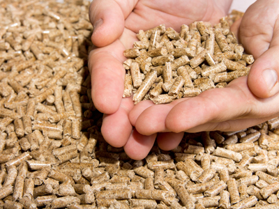 Figure 1: Example of pelleted biomass materials.A recent report submitted by the United Nations’ International Panel on Climate Change detailed grave expectations for the future of our planet. As per the report, human activities are estimated to have caused an approximately 1.0°C of global warming above pre-industrial levels, with a high likelihood that global warming will reach 1.5°C sometime between 2030 and 2052.
While several positive strides have been made in the development of renewable energy resources and systems, further efforts are needed to secure the safety of our world for future generations.
One example of a viable clean energy system alternative is the use of biomass boiler heating systems. These systems create energy through the combustion of carbon-neutral biomass materials (e.g. wood, corn husks, rice husks). The heat from this combustion process becomes the energy source to heat a residence or property, while the left over organic ash can be used as a fertilizer.
Biomass source materials are put through a pelleting process before delivery to a biomass hopper. This is done to ensure the uniformity of materials for optimal material flow, or rheology. The biomass pellets are then fed from the hopper and into the combustion system via an auger. However, once biomass pellets are added to a hopper, there is always a risk that the system can become clogged over time, and ultimately take the energy system offline.
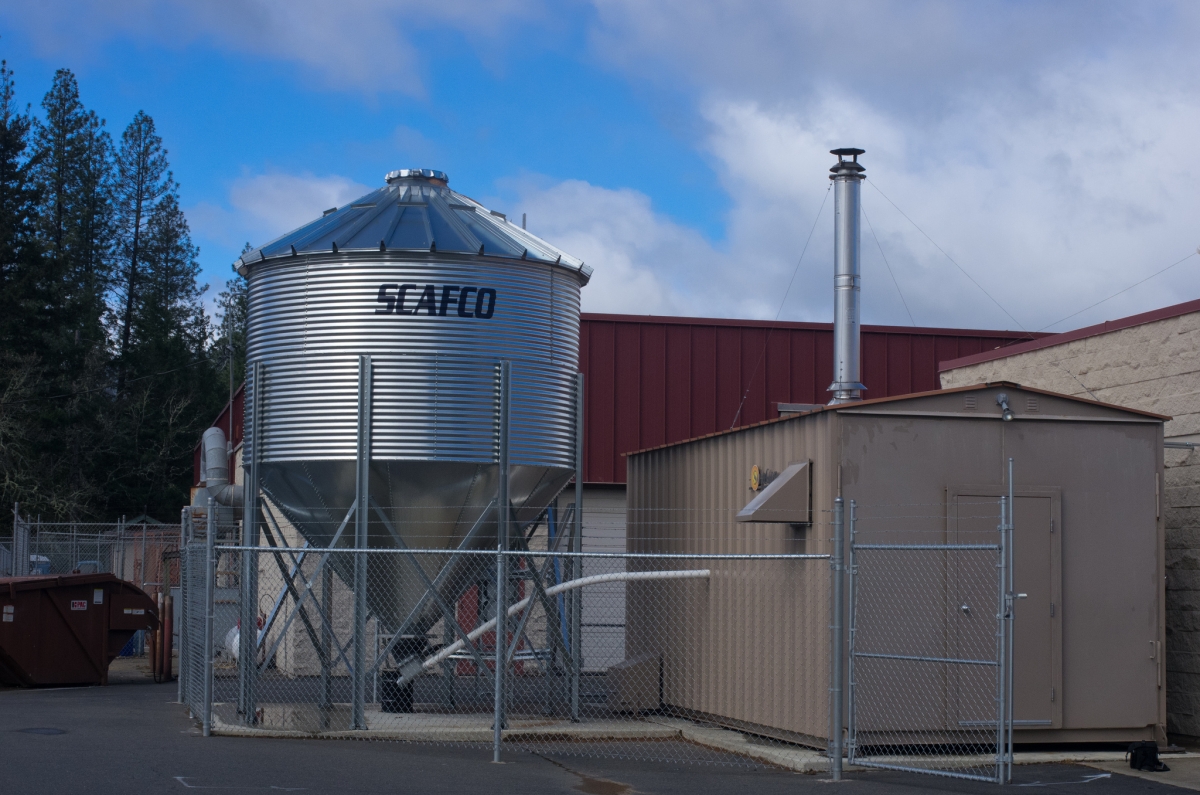 Figure 2: A biomass hopper (left) feeding into a biomass boiler room. Image courtesy of the Oregon Department of Forestry.One biomass hopper manufacturer wanted to gain deeper insight into their hopper designs, and understand how pressure distribution could play a role in the material flow. They used I-Scan™ pressure mapping technology to capture quantifiable information on how different types of biomass materials would collect and bunch together in different sections of the hopper.
The ultra-thin I-Scan sensors made it possible to conform around the hopper funnel and capture this information without impeding the flow of material. With this information, the design engineers could make adjustments their hopper designs to ensure a more efficient and better functioning system.
|
|
Biomass material flow assessment is just one way pressure mapping technology has helped forward designs for renewable and clean energy resources. For more power & battery pressure mapping applications, download this free eBook now!. |