
The Differences Between Force Sensitive Resistor Technologies: Assessing Linearity, Drift, and Other Performance Factors

Not all force sensitive resistors are created equal. There are significant performance factors that are important to consider before making your investment.
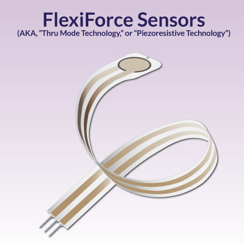
This article compares FlexiForce™ ultra-thin force-sensitive resistors (AKA, Thru Mode Technology) against Shunt Mode force sensitive resistors. We will cover some specific differentiating aspects between these two technologies that will be supported by verifiable, third-party data.
Flexiforce is the premium FSR choice based on 5 key measures of accuracy for your force sensing device. Compare for yourself, and read the published research.
Our goal at Tekscan is to always to provide our customers with the best possible force sensor solution for their application. The performance aspects we share are ones we feel are important to design engineers.
So, Here's What We're Working With:
 |
 |
|
Ultra-thin and flexible printed circuits consisting of two flexible substrates (polyester film).
|
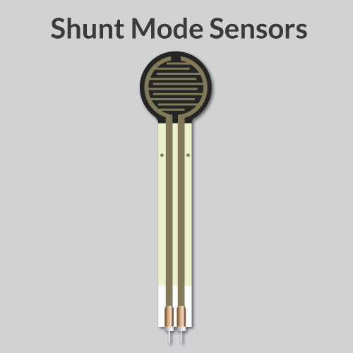
Polymer thick-film devices consisting of two membranes separated by a thin air gap.
|
When Unloaded, Resistance is High - When Pressed, Resistance Drops |
|

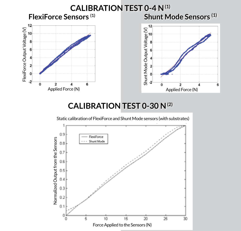
FlexiForce produced a more linear relationship in the two calibration tests featured below. In both tests, the Shunt Mode force sensitive resistor appeared particularly non-linear within the 0-4 N force range.

 |
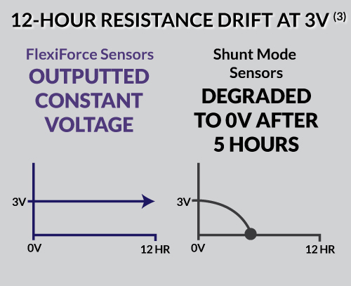 |
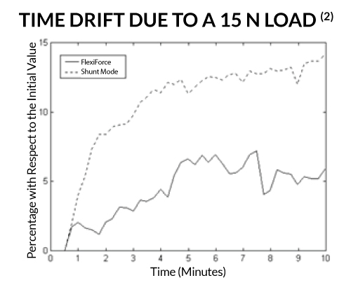
| In this test, the FlexiForce and Shunt Mode sensors loaded at 15 N for 10 minutes. The sensor output was sampled at a frequency of 20 Hz. As the results showed, the Shunt Mode sensor incurred a much greater percentage error with respect to the initial value over the loaded timeframe. | In this test, a FlexiForce A401 and a Shunt Mode sensor were placed into a tube for 12 hours. Voltage readings were recorded every minute. After five hours of testing, the voltage reading in the Shunt Mode degraded from 3V to 0V, while the FlexiForce output a constant voltage of about 3V for over 12 hours. In addition to not exhibiting resistance drift, the test also found the FlexiForce sensor could read forces up to 110 N within a 0.5 N accuracy. |

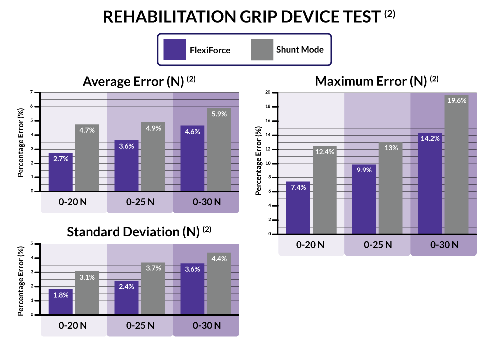
In this test, FlexiForce and Shunt Mode sensors were mounted onto the thumb of a rehabilitative gripping device. The subject wearing the device was instructed to pinch a strain gauge dynamometer varying the exertion force at a rate of one pinch every two seconds for a period of 10 seconds to determine the sensor response to slow dynamic loading. The test was replicated five times over three force ranges (0-20 N, 0-25 N, and 0-30 N). The total error at each force level was computed as the difference between the force measured using the dynamometer and the force obtained from the sensor output.
As the results show, FlexiForce was significantly more accurate than the Shunt Mode sensor at all three force ranges.

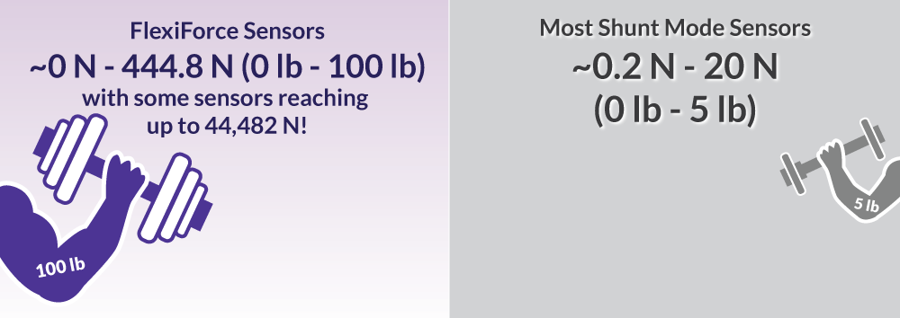
According to manufacturer specs, FlexiForce can capture a wider range of force with greater accuracy than a majority of Shunt Mode force sensing resistors. The force range of FlexiForce sensors can also be adjusted to match the needs of the application.

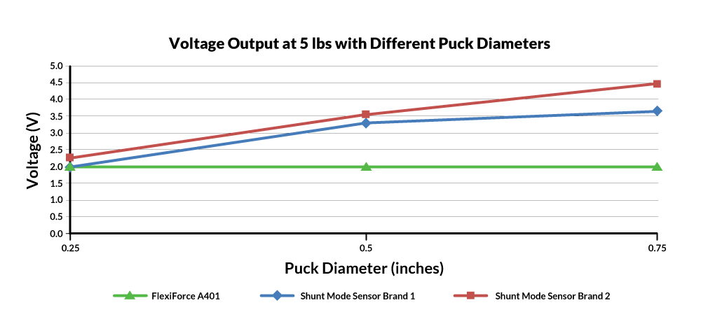
In this test, FlexiForce sensors delivered the same force output when step loaded with three different puck diameters, whereas two shunt mode sensor types showed inconsistent output. This data indicates that shunt mode sensor output is a function of both load area and applied force.
CHOOSE WISELY
While FlexiForce proved to be the better alternative in these tests, every application has its own unique challenges and may produce different results. Whether as a standard sensor or custom solution, our team of expert engineers is standing by to find the right FlexiForce solution to achieve your needs.
Click here to download an infographic summarizing this blog.
Visit our online store to browse our FlexiForce Standard Sensors. Leave any comments or questions you have in the comments forms below, or contact us today to discuss your application.
References
All testing comparing Flexiforce and Interlink FSR sensors was done by 3rd parties documented as follows:
1 Sadun, A.S., et. al. "Force Sensing Resistor (FSR): A Brief Overview and the Low Cost Sensor for Active Compliance Control." (2016) Faculty of Engineering Technology, Universiti Tun Hussein Onn Malaysia, 86400 Parit Raja, Batu Pahat, Johor, Malaysia
2 Vecchi, F. et. al. "Experimental Evaluation of Two Commercial Force Sensors for Applications in Biomechanics and Motor Control." Advanced Robotics Technology and Systems Laboratory. Scuola Superiore di Sant'Anna via Carducci 40, 56127 Pisa, Italy.
3 Benbourenane, I. "Design of Nasal Endoscopy Simulator with Force Feedback" (2014) Human Movement and Balance Lab of the University of Pittsburgh.)