Pressure Mapping For Magnetorheological Finishing Of Precision Optical Surfaces
Challenge
Conventional polishing typically involves abrasives and backing materials that result in minute cracks in the glass surface that translate into impairment of theoretical optical performance. Magnetorheological (MR) fluids are micrometer sized magnetic particles suspended in a carrier fluid, and "stiffened" by a magnetic field. There is no backing material.
Solution
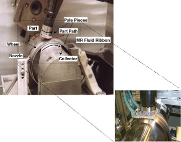
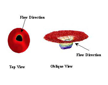
Sensor model 5051, shown in the inset of Figure 1, measures the forces normal to a stationary part due to hydrodynamic flow. Figure 2 shows a top view and oblique view of the "D" shaped removal "spot," representative of material removal without part rotation. Figure 3 shows a two dimensional pressure map provided by the I-Scan™ System. The 5051 sensor and I-Scan pressure mapping system facilitates experimentation with different magnetic fields, wheel rotation rates, and other geometric variations to optimize the polishing process.
|
|
|
Magnetorheological finishing (MRF) of precision optical surfaces offers the promise of improved surface characteristics compared to conventional polishing. Careful control of several factors including impact pressure distribution is crucial to achieving this potential. Properties of MRF in the polishing zone are difficult to study because the fluid is opaque, and the complex interactions of particles in the magnetic field are difficult to see or model with other techniques.
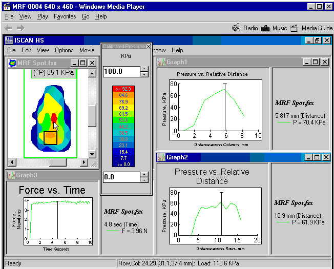 Figure 3. Lens Polishing Pressure Measurement Software