
Voltage Divider or Op Amp Circuit -- Which Should You Choose?
 Ed Haidar; FlexiForce Product Manager
Here's another question we frequently receive from our customers - what is the recommended circuit to drive a FlexiForce™ sensor in an embedded design? If you've browsed our standard FlexiForce sensors recently, you’ll notice that we recommend an Inverting Op Amp circuit. However, it is possible to power your FlexiForce sensor with many analog circuit configurations. The choice of circuit truly comes down to the specific force output resolution required in the application and anticipated force range.
For this article, we're specifically going to talk about the Voltage Divider and Op Amp Circuit.
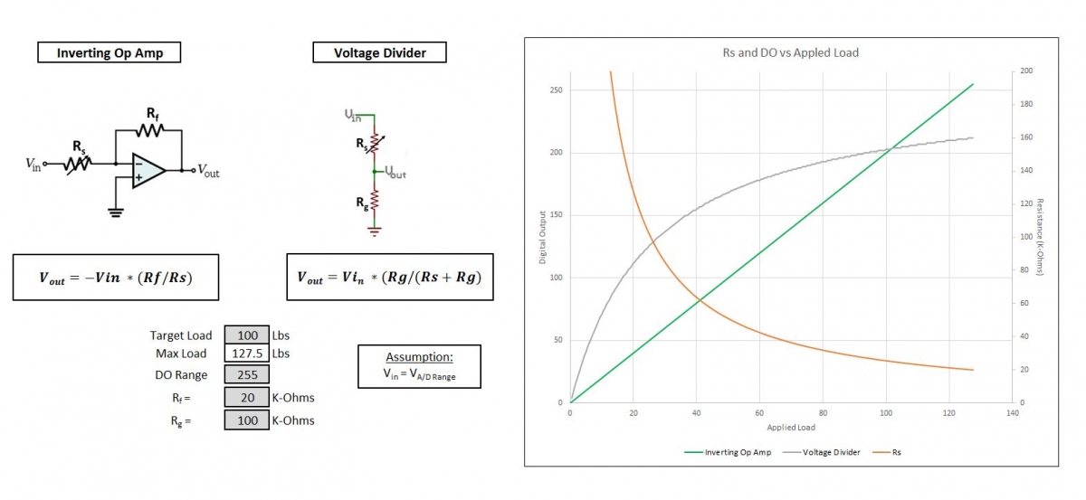 Figure 1: Raw force data of a FlexiForce sensor graphed on an 8-bit system (256 data points).
The orange line (Rs) in Figure 1 is an example of a typical resistance vs force curve of a FlexiForce sensor. When connected, the sensor's resistance is high, and drops as more force is applied. The other two lines in this graph map out a FlexiForce sensor performance in different circuits - a voltage divider (gray line) and an Inverting Op Amp (green line).
Both types of circuits will output a variable analog voltage as the sensor resistance changes as a function of applied force.
Let's get into the specific differences
Attributes |
Voltage Divider |
Op Amp |
| Cost | Can be more cost-effective than op-amp circuits. | More expensive than a Voltage Divider. However, it also provides the most versatility in terms of force range adjustment by adjusting the circuit parameters of the reference voltage and/or the feedback resistor. |
| Integration Complexity | Simple circuit operation – isolation needs to be accounted for when working with this circuit. | More complex. |
| Linearity | The linearity of a voltage divider circuit is not constant. This can be advantageous when a particular sensitivity is desired across a portion of the force range, and a different sensitivity is desired across the rest of the force range. | Shown in Figure 1, the Op Amp circuit maintains its linearity through a much wider force range. This makes Op Amp circuits more advantageous for applications that could have an unpredictable range of force applications over its use that require a constant sensitivity through the entire force range of the application. |
How Working with Tekscan Can Save You in Engineering Costs
Because FlexiForce sensors function as a resistor in an electrical circuit, any circuit that expresses a change in resistance can be used to power a FlexiForce sensor. This is why the circuit selection truly comes down to the needs of the application.
We have worked with hundreds of design engineers on the circuit selection process for their embedded design. After a brief consultation, we will recommend the best sensor resistance range for your application, and saving in both the cost of your circuit, and potential re-engineering time.
Interested in Speaking with a Tekscan Applications Engineer About FlexiForce Circuit Selection for Your Embedded Application? Contact Us Today!