Addressing Rail Seat Pressure Distribution Concerns
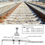 Figure 1: This diagram shows how the pressure mapping sensor (MBTSS) was positioned between the concrete rail seat, and bottom of the rail pad.
Challenge:
Concrete cross ties are typically used in railways that place high loading demands on track structure, and also to necessitate stringent geometric tolerances of the surrounding area. However, concrete cross ties do come with their design and performance challenges. Over time, the widening of gauge, reduction in claiming force (toe load) of fastening clips, and insufficient rail cant, can create potentially unsafe operating conditions.
Solution:
Transportation researchers with the University of Illinois Urbana-Champaign used pressure mapping technology to measure and quantify forces and pressure distribution acting at the contact interface between the concrete rail seat, and bottom of the rail pad. The diagram in Figure 1 shows how the sensor (referred as “MBTSS layers”) was placed between pad assembly and rail seat*.
The results indicated that lower-modulus rail pads could distribute rail seat loads over a larger contact area, reduce peak pressure values, and mitigate highly-concentrated loads at the interface, when compared to the higher-modulus rail pads. The research group is planning further rail pad component experimentations using pressure mapping technology in the future.
Similar Applications:
- Ballast-tie construction
- Railway suspension bridge construction
Source: Rapp, Christopher, et. al. “Measuring Rail Seat Pressure Distribution in Concrete Cross ties” University of Illinois Urbana-Champaign. Transportation Research Record: Journal of the Transportation Research Board, No. 2374 (2013) 190-200.
*Note: Sensor protection was required for this experiment.
Choose Your Next Destination! Select From the Icons Below
