Easily Embed Sensors in Your Product
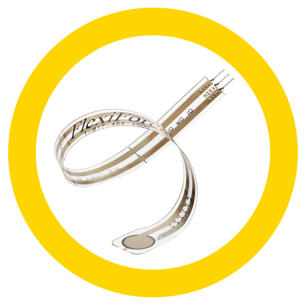
Our thin, customizable FlexiForce™ sensors are a cost effective force measurement solution for consumer products. With our engineering expertise, these sensors can easily be designed into products across various markets. These customizable sensors can be produced in high quantities with a quick design time. The sensors are ideal for consumer products due to their ability to withstand various storage temperatures and conditions.
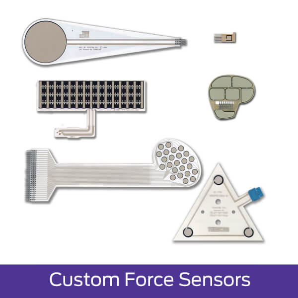
FlexiForce™ Custom Force Sensors
Choosing FlexiForce for your embedded force sensor application carries a variety of advantages over the competition, including:
- Superior linearity & accuracy (±3%)
- Expert technical guidance in custom solutions
- Wider range of forces
- Sensor output is not a function of loading area
- High temperature versions (up to 400°F) available
- Custom sensors are 100% tested to ensure they meet agreed-upon specifications
- We accept custom jobs with quantities as low as 1000 to as high as millions of sensors
To learn more about FlexiForce sensors and our custom capabilities, visit our Force Sensor Page
Our Expertise
Our experienced engineering team works closely with you throughout each stage of the design process to ensure the best sensor design for your application. For customers who need custom application software to complement their sensors, we team up with trusted partners to combine our expertise and develop complete specialized solutions.
In addition to our embedded force sensors, we have a complete product line of sensors for embedded systems that include matrix pressure mapping sensors and product design solutions.