T-Scan v10 uses Microsoft's SQL Server as its database engine. You must install SQL where you plan to locate your T-Scan database before upgrading T-Scan software on your operatory workstations. This is a one-time only step–once SQL is installed, future T-Scan updates will return to a single step process!
Local Configuration
If you plan to run T-Scan in a local configuration where your patient list is only accessible to one operatory workstation or a traveling laptop, you will be installing SQL to that workstation.
Instructions
- Your T-Scan software was emailed. Click on the downlink.
- Your downloaded software is compressed, so extract the software.
- Open the installation files and locate Autoplay.exe
- Right-click over that file and select "Run as administrator"
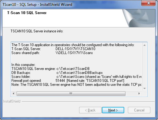
- Make note of the server path that gets displayed during the SQL set-up similar to the example shown below. This will be needed when you upgrade your T-Scan application on your operatory workstations
-
- Return to T-Scan on your operatory workstation and select " Help > Update" to update your T-Scan application. Follow the instructions located here to continue.
Network Configuration
If you have a Networked T-Scan license to centralize your patient database, these instructions are for you. You must have purchased a Network License Add-On to enable this functionality.
All references below to "server" relate to the computer that will be hosting your T-Scan database, not the workstations on which you will be running T-Scan.
Instructions
- Your T-Scan software was emailed. Click on the downlink.
- Your downloaded software is compressed, so extract the software.
- Open the installation files and locate Autoplay.exe
- Right-click over that file and select "Run as administrator"
- Make note of the server path that gets displayed during the SQL set-up similar to the example shown below. This will be needed when you upgrade your T-Scan application on your operatory workstations
.
- When complete, you will have successfully downloaded MS SQL. Return to T-Scan on your operatory workstation and select " Help > Update" to update your T-Scan application. Follow the instructions located here to continue.