MatScan™ with the Sway Analysis Module™
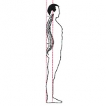
The patient was a nine year-old boy previously treated using chiropractic manipulations and the MatScan™ for displaced cervical vertebra and ribs, and blocked sacroiliac (SI) joint due to falls. He was diagnosed with the following: the first cervical vertebra (C1) was displaced with absence of left rotation; 2nd cervical vertebra (C2) displaced with absence of right rotation; 8th thoracic vertebra (T8) displaced with absence of extension; right 5th rib absence of motion; left 6th rib absence of motion; and left SI joint with absence of flexion (blocked). Visual body posture assessment also revealed segment misalignments. These included hip and shoulder drops and trunk anterior/posterior rotation.
Case History and Treatment Approach
The MatScan was used to measure and assess for first visit before-after (pre-post) manipulations, and in follow-up visits. The parameters captured and assessed were plantar pressure profiles, percentage body weight-bearing and percentage area of weight-bearing (contact) for left vs. right foot. Trajectory for the Center of Force (CoF) was also assessed. The Sway Analysis Module™ (SAM) was also used to calculate and display biomechanical parameters relating to body sway and weight-bearing of the feet.
Manipulations were done at the left pelvic SI joint, the spine at level of T8, T6 and T5, and the spine and head at level of C2 and C1. After manipulations, the MatScan revealed improvements with very similar pressure profiles, percentage weight-bearing and percentage contact area between the feet, indicating a corresponding improvement in posture. Reductions in weight-bearing shifting and CoF trajectory also indicated a corresponding reduction in body sway. The patient also stood more uniformly on his feet with reduced weight-bearing on the heels. Visual posture assessment revealed improvements with elimination of the hip and shoulder drops, and trunk rotation.
However, at a two week follow-up visit, the patient returned to his pre-treatment asymmetries, as evidenced with the MatScan, and misalignments, as evidenced by visual posture assessments. Manipulations were then repeated but to no avail. X-rays were finally prescribed and revealed the presence of limb length discrepancy (LLD) with the right side shorter. A right heel lift was prescribed and manipulations were repeated, which resulted in the symmetries and alignments remaining stable. Specifically, the pressure profiles, percentage weight-bearing and percentage contact area left vs. right foot were almost identical, with reductions in weight-bearing shifting and CoF trajectory. Patient also stood more uniformly on his feet, with less weight-bearing on the heels. Patient returned two weeks later for follow-up visit, and the symmetries and alignments were still present and in effect.
SAM Data & Analysis
Following is a screenshot from SAM with the recorded MatScan data. The displayed data is from a recording before the chiropractic manipulations and after the chiropractic manipulations, following use of the heel lift. The recordings were 15 seconds long at 40Hz (40 frames per second), and done standard in the same location, environment, time and day of week, while standing still and quiet with eyes open.

- In the pressure profile windows, the single last frame view of the recording is displayed. The black/white dots represent the location for the body CoF and the numbers represent percentage weight-bearing per respective quadrants for the frame displayed.
- The red and green ellipses represent the area in which the CoF traveled during the recording (all frames). The ellipse contour and area within the ellipses are calculated using a 95% CI (Confidence Interval). Centers of the ellipses are set at the median position of the Trajectory for the CoF.
